Study in detail about braking system used in various automobiles
1) BRAKE SYSTEM
2) TYPES OF BRAKE
3) FUNCTIONS
4) CONSTRUCTION
5) REFRENCES
BRAKING SYSTEM:-
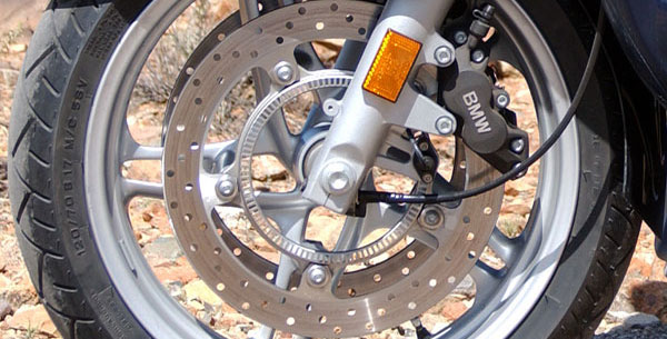
Disc brake on a motorcycle.
A brake is a device which inhibits motion. Its opposite component is a clutch. The rest of this article is dedicated to various types of vehicular brakes.
Most commonly brakes use friction to convert kinetic energy into heat, though other methods of energy conversion may be employed. For example regenerative energy converts much of the energy to electrical energy; other methods convert kinetic energy into potential energy in such stored forms as pressurized air or pressurized oil. Still other braking methods even transform kinetic energy into different forms, for example by transferring the energy to a rotating flywheel.
Brakes are generally applied to rotating axles or wheels, but may also take other forms such as the surface of a moving fluid (flaps deployed into water or air). Some vehicles use a combination of braking mechanisms’, such as drag racing cars with both wheel brakes and a parachute.
Since kinetic energy increases quadratic ally with velocity (K = mv2 / 2), an object traveling at
Almost all wheeled vehicles have a brake of some sort. Even baggage carts and shopping carts may have them for use on a moving.
Friction brakes on automobiles store braking heat in the drum brake or disc brake while braking then conduct it to the air gradually. When traveling downhill some vehicles can use there engine brake.
When the brake pedal is pushed a piston pushes the pad towards the disc brake which slows the wheel down. On the drum brake it is similar as the cylinder pushes the shoes brake towards the drum which also slows the wheel down.
TYPES OF BRAKE:-
Brakes may be broadly described as using friction, pumping, or electromagnetics. One brake may use several principles: for example, a pump may pass fluid through an orifice to create friction.
Frictional brakes are most common and can be divided broadly into "shoe" or "pad" brakes, using an explicit wear surface, and hydrodynamic brakes, such as parachutes, which use friction in a working fluid and do not explicitly wear. Typically the term "friction brake" is used to mean pad/shoe brakes and excludes hydrodynamic brakes, even though hydrodynamic brakes use friction.
Friction (pad/shoe) brakes are often rotating devices with a stationary pad and a rotating wear surface. Common configurations include shoes that contract to rub on the outside of a rotating drum, such as a band brake; a rotating drum with shoes that expand to rub the inside of a drum, commonly called a "DRUM BRAKE", although other drum configurations are possible; and pads that pinch a rotating disc, commonly called a "DISC BRAKE". Other brake configurations are used, but less often. For example, PCC TROLLY” brakes include a flat shoe which is clamped to the rail with an electromagnet; the murphy braking pinches a rotating drum, and the Ausco Lambert disc brake uses a hollow disc (two parallel discs with a structural bridge) with shoes that sit between the disc surfaces and expand laterally.
Pumping brakes are often used where a pump is already part of the machinery. For example, an internal-combustion piston motor can have the fuel supply stopped, and then internal pumping losses of the engine create some braking. Some engines use a valve override called a Jake brake to greatly increase pumping losses. Pumping brakes can dump energy as heat, or can be regenerative brakes that recharge a pressure resivoir called an hydraulic accumulator.
Electromagnetic brakes are likewise often used where an electric motor is already part of the machinery. For example, many hybrid gasoline/electric vehicles use the electric motor as a generator to charge electric batteries and also as a regenerative brake. Some diesel/electric railroad locomotives use the electric motors to generate electricity which is then sent to a resistor bank and dumped as heat. Some vehicles, such as some transit buses, do not already have an electric motor but use a secondary "retarder" brake that is effectively a generator with an internal.
1) DISC BRAKE:-
Close-up of a disc brake on a car
On automobiles, disc brakes are often located within the wheel
The disc brake or disk brake is a device for slowing or stopping the rotation of a wheel while it is in motion. A brake disc is usually made of cast iron, but may in some cases be made of composites such as corbon-corbon or ceramic matrix composites. This is connected to the wheel or the axel. To stop the wheel, friction material in the form of brake pads is forced mechanically ,hydraulically, pneumatically or electromagnetically against both side of the disc. Friction causes the disc and attached wheel to slow or stop. Brakes convert motion to heat, and if the brakes get too hot, they become less effective, a phenomenon known as brake fade.
Disc-style brakes development and use began in England in the 1890s. The first caliper-type automobile disc brake was patented by Frederick William Lanchester in his Birmingham, UK factory in 1902 and used successfully on Lanchester cars. However, the limited choice of metals in this period, meant that he had to use copper as the braking medium acting on the disc. The poor state of the roads at this time, no more than dusty, rough tracks, meant that the copper wore quickly making the disc brake system non-viable. It took another half century for his innovation to be widely adopted.
Modern-style disc brakes first appeared on the low-volume Crowley Hotshot in 1949, although they had to be discontinued in 1950 due to design problems. Chrysler's Imperial also offered a type of disc brake from 1949 through 1953, though in this instance they were enclosed with dual internal-expanding, full-circle pressure plates. Reliable modern disc brakes were developed in the UK by Dunlop and first appeared in 1953 on the Jaguar C-Type racing car. The Citroën DS of 1955, with powered inboard front disc brakes, and the 1956 Triumph TR3 were the first European production cars to feature modern disc brakes. The first production car to feature disc brakes at all 4 corners was the Austin-Healey 100S in 1954. The first British company to market a production saloon fitted with disc brakes to all four wheels was Jensen Motors Ltd with the introduction of a Deluxe version of the Jensen 541 with Dunlop disc brakes.[4] The next American production cars to be fitted with disc brakes were the 1963 Studebaker Avanti , standard equipment on the 1965 Rambler Marlin , and the 1965 Chevrolet Corvette Stingray. The 1965 Ford Thunderbird came with front disc brakes as standard equipment. The first German production car with disc brakes was the Mercedes W112 300SE with Dunlop brakes.
Compared to drum brakes, disc brakes offer better stopping performance, because the disc is more readily cooled. As a consequence discs are less prone to the "brake fade" caused when brake components overheat; and disc brakes recover more quickly from immersion (wet brakes are less effective). A drum brake will have at least one leading shoe, which gives a servo-effect; see leading. By contrast, a disc brake has no self-servo effect and its braking force is always proportional to the pressure placed on the brake pad by the braking system via any brake servo, braking pedal or lever.
Many early implementations for automobiles located the brakes on the inboard side of the driveshaft, near the differential, but most brakes today are located inside the road wheels.
Disc brakes were most popular on sports cars when they were first introduced, since these vehicles are more demanding about brake performance. Discs have now become the more common form in most passenger vehicles, although many (particularly light weight vehicles) use drum brakes on the rear wheels to keep costs and weight down as well as to simplify the provisions for a parking brake. As the front brakes perform most of the braking effort, this can be a reasonable compromise.
2) MURPHY BRAKE:-
The murphy brake is a drum brake with shoes that pinch the drum via a rotating fork. In contrast, most drum brakes use either shoes that press only on the inside of the drum, or shoes that press only on the outside of the drum, like a band brake. Like many drum brakes, the Murphy brake is self-assisting, so a low application force gives a high brake force. Like a disk brake, and unlike most drum brakes, the Murphy brake uses short shoes so braking force is less sensitive to changes in the coefficient of friction, for example as the drum and pads heat up. By using a "pinch" configuration, a relatively light drum can tolerate high pad forces, thus allowing use of pads with low coefficient of friction. The drum is slightly tapered or "bell mouthed", and the shoes are mounted movably so the brake drum can change shape as it heats and the pads will follow the change, without interfering with the brake's operation. The brake is named after its inventor, John H. Murphy.
A Murphy brake was fitted to the transmission of a front-engine school bus and operated via a mechanical linkage. A bus has an unusually long driveshaft, which is somewhat springy, so tends to exaggerate grabbiness: a grabby brake makes the driveshaft wind up, rather than turning the brake. When the driveshaft is sufficiently wound up, it overcomes the brake, which suddenly "lets go", leading to pulsing brakes or skids. The Murphy brake used sintered bronze shoes for smoothness.
The bus was tested for panic stop braking distance and was tested with both cold and hot brakes. With the Murphy brake on the transmission, the stopping distance under hard braking was the same as with wheel-mounted drum brakes.
3) BAND BRAKE:-
A band brake is a primary or secondary brake, consisting of a band of friction material that tightens concentrically around a cylindrical piece of equipment to either prevent it from rotating (a static or "holding" brake), or to slow it (a dynamic brake). This application is common on winch drums and chain saws and is also used for some bicycle brakes.
Band brakes can be simple, compact, rugged, and can generate high force with a light input force. However, band brakes are prone to grabbing or chatter and loss of brake force when hot. These problems are inherent with the design and thus limit where band brakes are a good solution. One way to describe the effectiveness of the brake is as eμθ, where μ is the coefficient of friction between band and drum, and θ is the angle of wrap. With a large μθ, the brake is very effective and requires low input force to achieve high brake force, but is also very sensitive to changes in μ. For example light rust on the drum may cause the brake to "grab" or chatter, water may cause the brake to slip, and rising temperatures in braking may cause the coefficient of friction to drop slightly but in turn cause brake force to drop greatly. Using a band material with low μ increases the input force required to achieve a given brake force, but some low-μ materials also have more consistent μ across the range of working temperatures.
Vehicle brake:-
A vehicle brake is a brake used to slow down a vehicle by converting its kinetic energy into heat. The basic hydraulic system, most commonly used, usually has six main stages. The brake pedal, the brake boost (vacuum servo), the master cylinder, the apportioning valves and finally the roadwheel brakes themselves.
4) Ausco Lambert disc brake:-
The Ausco Lambert disc brake is an unusual brake where an axially-expanding shoe assembly is sandwiched between two linked rotating discs. It may be thought of as an "inside out" disc brake: instead of pads pinching a disc, the pads expand inside a hollow disc.
The Ausco Lambert brake also has an unusual mechanism to expand the pads. It uses two flat rings, both with pad material on one side and conical divots on the other side. Two rings are placed together with the conical divots facing together and a ball bearing in each pair of divots. When the rings are rotated relative to each other, the balls roll up the ramp faces of the conical divots, pushing apart the two rings.
The Ausco Lambert brake is self-energizing. It holds one ring rigidly and lets the other rotate freely, without a stop. The rotation direction is arranged so the direction of free rotation is the same as the hollow brake "disc". Thus, the disc tends to pull the ring in the direction that further applies the brake. A shallower cone angle increases the amount of self-energizing effect. Self-energizing brakes are more subject to brake fade, but it appears part of the Ausco Lambert design is to reduce the exponential gain of drum and band brakes, and thus reduce grabbiness and hot fade.
When the disc rotates the opposite direction of ring rotation, the brake tends to self-release. This is common also for drum brakes and is acceptable for uses where hard braking is in one direction.
Ausco Lambert brakes were introduced about 1950 and used commercially in some Chrysler cars and some Farm all tractors. Chrysler reportedly used either too few cones and balls, or cones or balls that were not hard enough given the number used; they could deform under brake load, leading to brake failures.[2] Chrysler returned to conventional drum brakes and stopped further development of the Ausco Lambert brake.
5) Compression release engine brake:-
A compression release engine brake, frequently called a Jake brake or Jacobs brake, is an engine braking mechanism installed on some diesel engines. When activated, it opens exhaust valves in the cylinders, releasing the compressed air trapped in the cylinders, and slowing the vehicle.
Although Jake brake properly refers to the Jacobs brand of engine brakes, the term has become a genericized trademark and is often used to refer to engine brakes or compression release engine brakes in general, especially on large vehicles or heavy equipment
FUNCTION:-
When the driver releases the accelerator on a moving vehicle powered by a diesel engine, the vehicle's forward inertia continues to turn the engine's crankshaft, drawing air into the cylinders as the pistons move down and compressing that air as the pistons move back up. The pressure of the compressed air pushes back on the up-going piston, tending to slow the vehicle.
But, without a compression release mechanism, as the piston passes through top dead center and heads back down again, the compressed air in the cylinder acts as a spring and pushes the piston down, returning most of the work done in compression back to the crankshaft, tending to accelerate the vehicle. The net effect is that the engine turns freely and the vehicle coasts.
When a compression release engine brake is active, a valve releases the pressure from the cylinder before the piston starts back down, so the slowing effect is present on the up stroke, but no accelerating effect is present on the down stroke and the net effect is the vehicle slows down.
With a gasoline engine, the mechanics are different and a special valve is not necessary for engine braking to happen when the driver releases the accelerator. In the gasoline engine, with the accelerator released, a throttle prevents the free flow of air into the cylinders, so there is little pressure to release at the top of the compression stroke. The throttle itself provides engine braking through friction in the air flowing through it. But a diesel engine does not have a butterfly valve to limit air on the intake side.
A compression release engine brake uses an extra lobe on the camshaft to open a second exhaust valve at the top of the compression stroke. The stem of this valve telescopes during normal operation so the valve remains closed, but is locked at full length by a solenoid when the engine brake is engaged so that the valve opens as directed by the cam. This releases the compressed air in the cylinder as described above.
The driver controls consist of an on/off switch and, sometimes, a multi-position switch that controls the number of cylinders on which the brake is active. When the driver has turned on the compression release engine brake, it will activate when the driver releases the accelerator. There are also switches on the clutch and accelerator pedals that deactivate the compression brake when the driver disengages th
e clutch or presses the accelerator.
The name is derived from the manufacturer, Jacobs (of drill chuck fame), and was patented 1962-'65 by Clessie Cummins.
Electromagnetic brake
Electromagnetic brakes operate electrically, but transmit torque mechanically. This is why they used to be referred to as electro-mechanical brakes. Over the years, EM brakes became known as electromagnetic, referring to their actuation method. Since the brakes started becoming popular over sixty years ago, the variety of applications and brake designs has increased dramatically, but the basic operation remains the same.
Single face electromagnetic brakes make up approximately 80% of all of the power applied brake applications. This article mainly concentrates on these brakes. Alternative designs are shown at the end of this article.
CONSTRUCTION:-
A horseshoe magnet (A-1) has a north and south pole. If a piece of Iron contacts both poles, a magnetic circuit is created. In an electromagnetic brake, the north and south pole is created by a coil shell and a wound coil. In a brake, the armature is being pulled against the brake field. (A-3) The frictional contact, which is being controlled by the strength of the magnetic field, is what causes the rotational motion to stop. All of the torque comes from the magnetic attraction and coefficient of friction between the steel of the armature and the steel of the brake field. For many industrial brakes, friction material is used between the poles. The material is mainly used to help decrease the wear rate. But different types of material can also be used to change the coefficient of friction (torque) for special applications. For example, if the brake was required to have an extended time to stop or slip time, a low coefficient material can be used. Conversely, if the brake was required to have a slightly higher torque (mostly for low RPM applications), a high coefficient friction material could be used.
In a brake, the electromagnetic lines of flux have to attract and pull the armature in contact with it to complete brake engagement. Most industrial applications use what is called a single-flux two-pole brake. The coil shell is made with carbon steel that has a combination of good strength and good magnetic properties. Copper (sometimes aluminum) magnet wire, is used to create the coil, which is held in shell either by a bobbin or by some type of epoxy/adhesive.[2]
To help increase life in applications, friction material is used between the poles. This friction material is flush with the steel on the coil shell, since if the friction material was not flush, good magnetic traction could not occur between the faces. Some people look at electromagnetic brakes and mistakenly assume that, since the friction material is flush with the steel that the brake has already worn down but this is not the case.
Anti-lock braking system:--
An anti-lock braking system (ABS) is a safety system that prevents the wheels on a motor vehicle from locking up (or ceasing to rotate) while braking.
A rotating road wheel allows the driver to maintain steering control under heavy braking by preventing a skid and allowing the wheel to continue interacting traction with the road surface as directed by driver steering inputs. ABS offers improved vehicle control and decreases stopping distances on dry and especially slippery surfaces for many drivers, but on loose surfaces like gravel and snow-on-pavement it can slightly increase braking distance, while still improving vehicle control.
Since initial widespread use in production cars, anti-lock braking systems have evolved considerably. Recent versions not only prevent wheel lock under braking, but also electronically control the front-to-rear brake bias. This function, depending on its specific capabilities and implementation, is known as electric brake force distribution (EBD), traction control system, emergency brake assist, or electronic stability control.
REFFERENCE:-
1) http://www.the-automover.com/Brake-system.htm
2) http://www.familycar.com/brakes.htm
3) http://en.wikipedia.org/wiki/Disc_brake
4) http://auto.howstuffworks.com/auto-parts/brakes/brake-types/brake.htm
5) http://www.tpub.com/content/engine/14105/css/14105_33.htm
6) http://www.freepatentsonline.com/6752473.html
7) http://www.fjhuari.com/?m=USER104153&l=en
8) http://eng.lynf.cn/Series1/?gclid=CI23gsmMhKUCFUJB6wodFTC-PA
9) http://www.mayfren.com/?gclid=CIC849KMhKUCFcxA6wodGhmKNw
10) http://www.avn.dk/AVN/hydraulik?gclid=CJaTxsaMhKUCFVFB6wodYi7HOA


